
I absolutely love distance maps, and I wanted to do this post for a long time, but it’s a lot of work preparing and writing these things. Massive respect to folks who do stuff like this all the time, I guess I know now why people charge money for good tutorials lol. Not that I’ll do that. Not that I think this is a good tutorial. That’s up to you to decide. Let’s just say I don’t believe in learning by copying – I’m much more fond of learning by using brain. That’s why I won’t go into too much detail on how to -exactly- copy what I’ve done. I’ll show you the principle, you work it out. Deal? Great. Let’s get started then!
D=?So, what is a distance map, you ask? Well, it’s a funky procedural map that works by assigning user-defined color values to your objects by calculating the distance from any point of your object[s] to some other, also user-defined, geometry. But nerdy definition aside, distance maps are a very powerful and flexible tool which you can use for a lot of different effects, some of which I will demonstrate below.
We’ll be looking at CoronaDistance, but in V-Ray the functionality of the VrayDistanceTex is practically the same, and they have a similar UI, so what works with one should work with the other as well [with some exceptions which we will conveniently ignore, I have only so much free time to write this, and there’s a guy coming to patch up a hole in my wall so I have to move the computer… and no, the hole is there because I had gas pipes installed, not because I was overly aggressive towards said wall. I’m a nice guy, ask anyone].
Let’s take a peek at the UI:
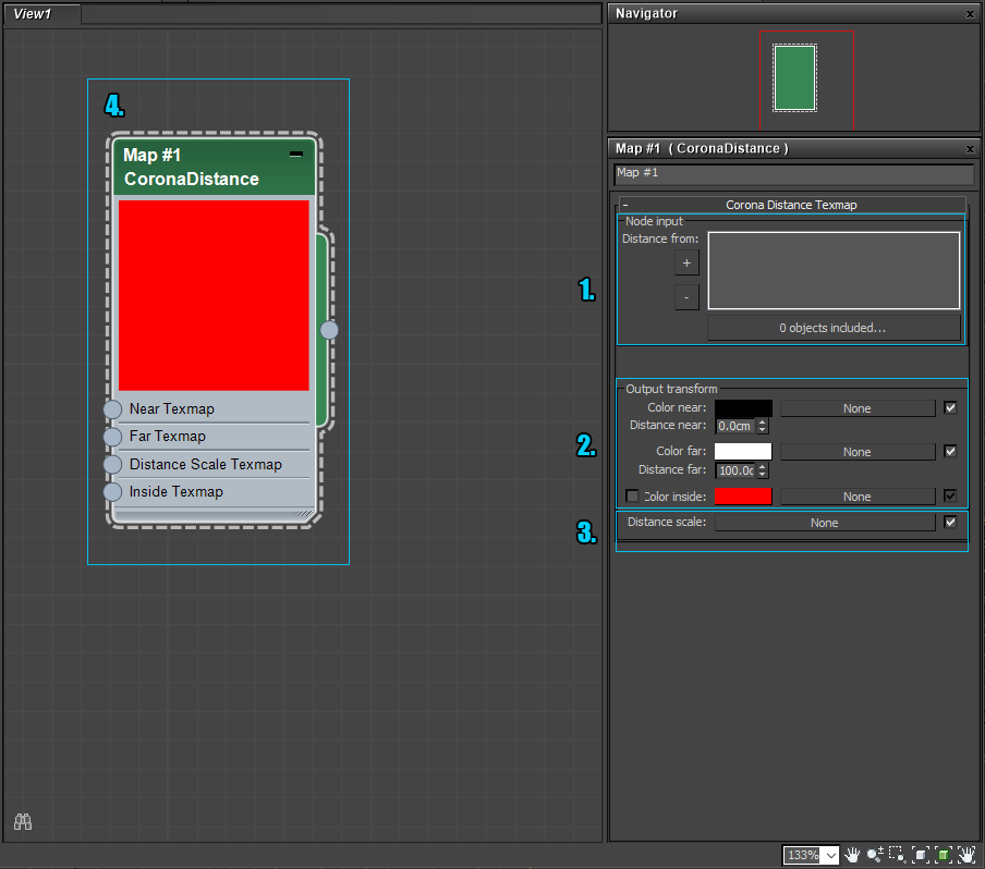
1. Node input: This is where you’ll put the objects the distance map will test against. I.e. NOT the object you will apply it to, since in that case the map would want to calculate the distance of an object to itself. [At which point the object would enter a state of questioning the nature of self, the universe would implode, or you’d get a warning about a dependency loop in your scene. One of those three, in any case.]
2.Output transform: This is the place to put your colors/maps in.
Any point of the object with a distance less or equal to “Distance Near” will have the “Color Near” assigned to it.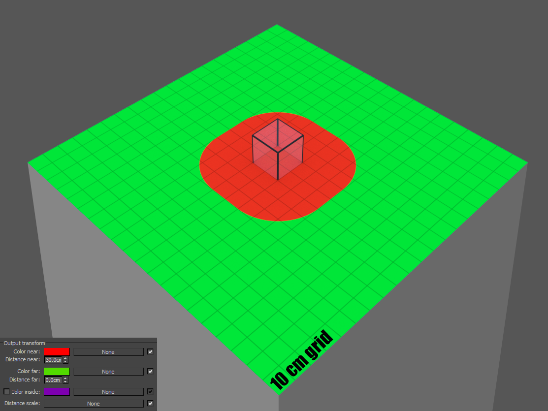
Likewise, any point of the object with a distance greater or equal to “Distance Far” will have the “Color Far” assigned to it. [Nobody would have guessed that one!] The color will fade from “Color Near” to “Color Far” between those two distances.

Finally, any point of the object inside the target object will have the “Color Inside”, if it is enabled.

3. Distance Scale: This map multiplies the “Distance Near” and “Distance Far” values and can be used for different effects. In this case a turbulence noise map was plugged into the slot. A value of 1 or pure white in the map will leave the values unchanged while anything darker will reduce the distance values.

4. Preview: Whatever. [Due to the nature of the Distance map, this preview is as useful as a pocket Bible in case you just jumped off a plane and both your main and secondary parachutes failed to open.]
Phew… Now that the boring stuff is over with, let’s have some fun! I’ll show you a few examples what can be achieved with Distance maps, but the most important thing to keep in mind when using them is to be creative! There’s tons of potential uses for these babies, you just need to think outside the box. [Well… or inside the box I suppose, if the box has flipped normals. Hmm…come to think of it, could a box with backface culling be considered a Schrödinger’s Box?]
Serious stuff starts here. No bad jokes, pinky promise. [But although pretty basic, I’ll be damned if this particular chapter’s name doesn’t sound like something from a Siggraph whitepaper.] If you set the near and far distances to 0.00 and both colors to white, then enable the inside color and set it to black, you can plug the map into the opacity slot of your material, effectively creating a rendertime clip object. Note that the objects you’re getting the distance from don’t have to be renderable! [Just uncheck renderable in the object properties panel.]

As you can see, I just added an animated noise to the plane to illustrate the effect.
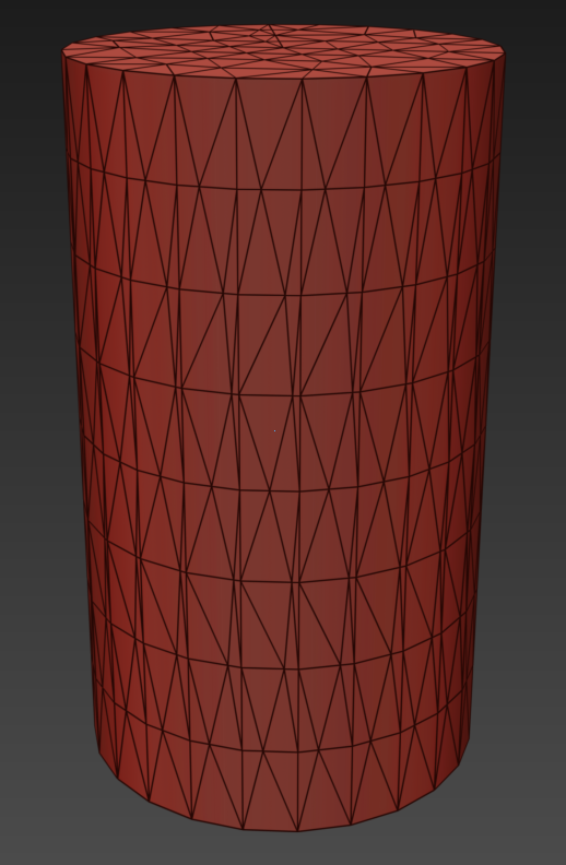 So the first one was pretty simple. Let’s try something different. Let’say you have a model with horrible topology. But for some reason you need to add a hole with a screw in it. [Happened to me more than once, true story.] Let’s also say you’re not entirely sure where the screw should go, so you need to show something to the client and later maybe change it. Instead of modeling and remodeling and ultimately rage-quitting, you can use some distance+displacement trickery. Imagine this was our original model on the right.
 Now, create and attach 2 identical perpendicular boxes, to form a cross shape like so:
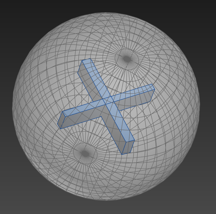 Then create a sphere around the cross and align those two objects by center:
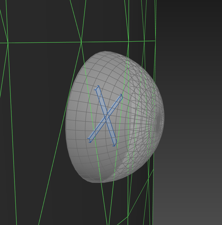 Place the helper objects on the surface of the main object where you want to add screws:
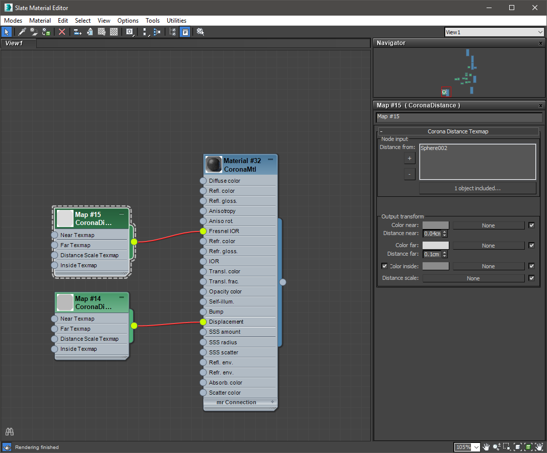
Now let’s create our first distance map. Add the crosses and spheres to the target nodes, plug the map into the displacement slot and start playing with the values. [A great way to quickly check how your distance maps look is to plug them into the diffuse slot temporarily, that way you’ll get a better feeling of how the colors and distances work for your particular object.]
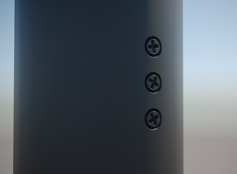
If you get it right, you’ll get something like the picture on the right. But what’s a screw if it ain’t metal, right? In order to do that, we have to create another distance map. We’ll add just the spheres to the node list this time though. Plug this new map in the Fresnel IOR slot.
And after some fiddling with the values you’ll hopefully end up with something like the next pic. [Because of the difference in scale, you’ll have to do that on your own and not copy mine – like I said at the start, that would be way too easy and this ain’t kindergarten :*] 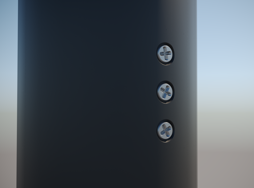
Whaddayaknow, insta-screws! Neat, right? Bear in mind this method usually won’t live up to close scrutiny but can still come in handy a lot of times. Below is another example of what you can do with this method. Suffice to say it’s the exact same principle as above, just a bit more complicated. Some hidden geometry and two distance maps mixed together to form the final displacement map – one for the actual tracks, and one for the snow spatter around them. 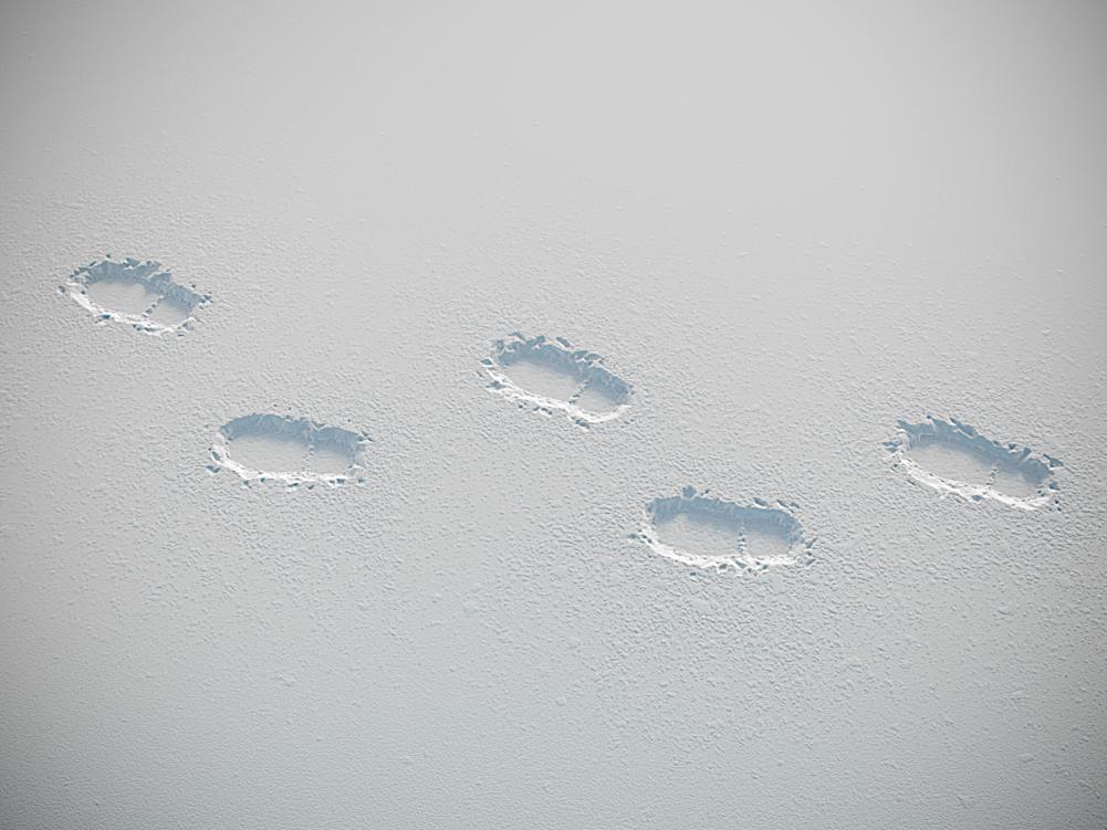 3. Geometry driven material masking or Distance map VS the nasty architect
[No bad jokes promise applied only to the previous chapter.] This one is fun! Much alike the previous example, you can use invisible helper geometry to mask and/or combine different maps and materials. To demonstrate that, we’ll use a hypothetical house by a hypothetical [nasty] architect. And not just any house but this architectural marvel: 
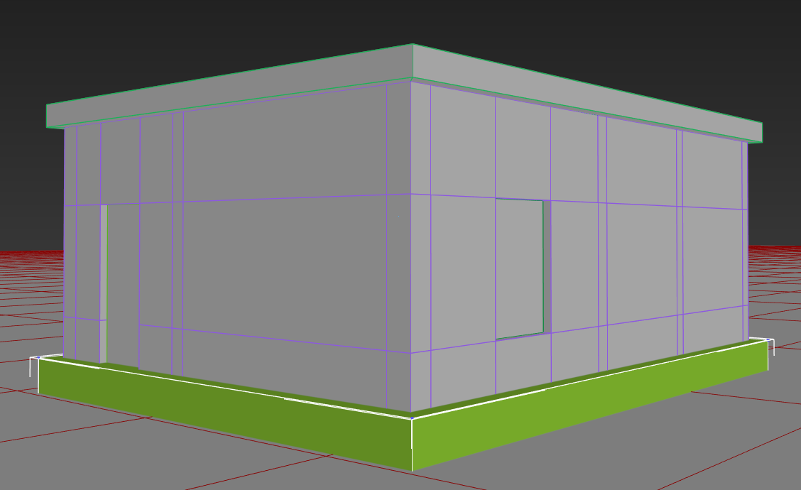 So… You got the plans, you modeled the house. Alas, the nasty architect, in a particularly bothersome episode of distaste, decided the facade needs a plinth of sorts, with a different material of course. And a border between the plinth and wall just for good measure. What he doesn’t know is that we have the power of the distance map and we don’t care because it’s EZ AF. We know that we’ll need some helper geometry again, so let’s add a box around the base of the house.
Next we need some distance maps. We’ll make one for the border, and one for the area inside of the box so we can use them as masks. Add the helper box to both distance maps and make it unrenderable. [<- is that even a word?]
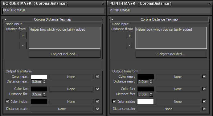
This is how I set up my masks. [And yes you lazy person you, this time you can copy actual numbers.]
 And this is how the finished material looks:
 Nothing really fancy to look at. In section 1 you see both masks. In section 2 we mix the wall texture with the border color on multiply using the border mask. Ditto for plinth color. In section 3 we mix the regular wall normal with a flat normal color for the border [which is 127,127,255, but if you don’t want to remember that, you can add an empty CoronaNormal map and just color pick from its preview], again using the border mask, and again mix that with the more rough plinth normal map. Finally for a bit of added flair we connect the border mask into the displacement slot with a -0,5cm displacement value. [Now the nasty architect can be happy because he got what he wanted, while we can be happy as well because we didn’t mess with modeling or material IDs at all.]
Apply this material to the house and lo and behold:

 Sweet! And all that without hurting any innocent polygons. But… curses! Our nasty architect realized he isn’t happy after all, because now he wants the same scheme around the doors and windows. Ah well… a few clicks later, problem solved. You can now go have a well deserved beer while enjoying your superiority and the fact you delivered the changes without actually doing any heavy lifting.
  And here’s another example of a similar setup, but animated. Some random concrete drying in the sun [of course the teapot is wearing sunscreen, we’re not animals]:
 This time there’s a single distance map with a moving helper box to influence the normal map, glossiness and add a bit of darkening to the diffuse map. By controlling the shape and animation of the helper object you can direct which areas get dry first.
And I’m only semi-joking. Like I said at least a few times already, there’s tons of potential uses given that you can do whatever you like with the helper geometry and mix them with other maps to your heart’s content. Also, distance maps are a very non-destructive way of doing different stuff, so it might come in handy, you never know. Just a bit of fair warning – using them with very detailed geometry [as in large polycounts] will make them really slow. That’s it. We’re done. If you reached this line without skipping anything that’s 50 extra points. Well done and see you in the next one!